Classic PMs
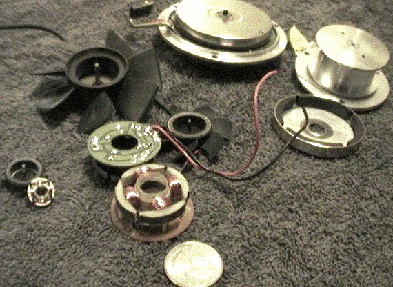
The classic permanant magnet (PM) motor (a.k.a. "brushless DC motors") can be found in older computer CPU and Power supply fan motors, and in very old hard disks, shown respectively. Four coils on the stator (and four poles on the magnet) are usual distinguishing feature. Most often the rotor, with PMs arranged in alternating north/south poles, is on the inside rim of a cup shaped metal shield, which rotates around the outside of the stator, rather than the "traditional" configuration you might find in old textbooks where the stator is on the outside.
These motors usually are designed to only spin one way, and are controlled by an oscillator made from diodes, resistors, capacitors, and transistors soldered onto a circuit board. Often the circuit board is inside the motor itself, underneath the stator. This control circuit generates an AC wave from DC power that is supplied to the motor -- (sometimes two sine wave with one slightly delayed from the other.) It turns the two sets of opposing coils positive and negative in turn, attracting north and south PM poles on the rotor alternately.
Various tricks, depending on the specific motor, are employed to help the motor spin up from a stop, and to determine the direction the motor spins. Most of the time a sensor (usually a "hall sensor") detects where the magnets on the rotor are, and the sine wave is delayed until the motor is where it is supposed to be. Often in order to save on the cost of the circuit board, a second, sometimes weaker, "winding" is wrapped along with the main coil. This allows a second AC wave to play with the magnetic field somehow (I won't go into it; it varies with the motor in question.)
3-phase PMs
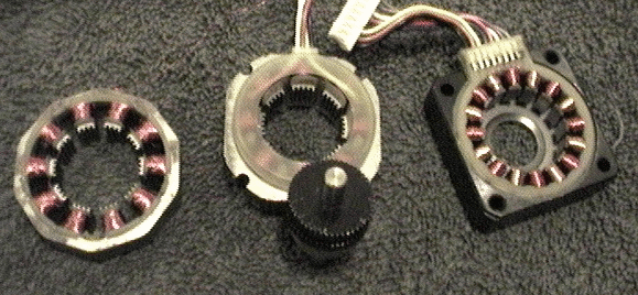
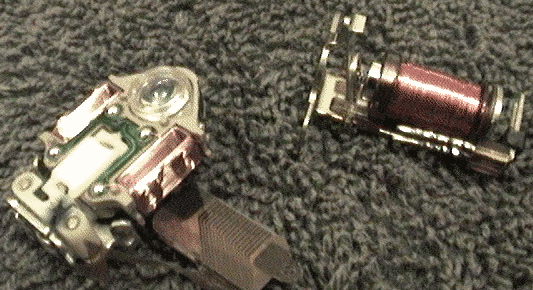
Three phase permanant magnet motors work basically the same way, and are very prevalent in most places where precise speed control is needed. That means spindle/platter motors for computer CD-roms, floppies, and hard disks. The number of regularly spaced coils is a multiple of 3, usually six. Three phase motors are popular for the same reason three phase electric power is popular (you may only use two phases at home but power companies use three most everywhere) -- three phases deliver the smoothest power. A good diagram is here.
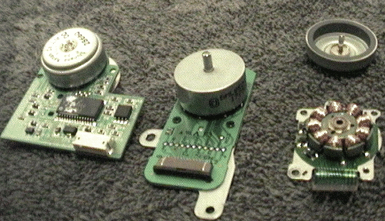
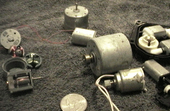
Three phase motors usually have a much more sophisticated controller, using a microchip on the circuit board. Often the circuit controlling a three-phase motor is outside of the motor, attached by a plug to the sensors and coils. Here are typical CD-rom spindle/platter motors -- the first has the controller "onboard" and the second just has a plug to attach to a controller. CDs are lower speed motors than hard drives, but are still fairly high RPM. They tend to be small and have few coils.
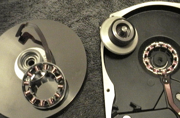
Next we see hard drive motors. They have six, nine, or twelve coils, and you may occasionally find them in the "traditional" configuration with the rotor inside the stator, as in the second picture, or in newer drives you'll often find they are embedded into the chassis with glue, and for hobbyists are best used that way rather than trying to extract them and mount the stator to something else. These tend to have very good bearings on them and are fairly sturdy compared to the rest of the motors shown.
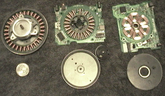
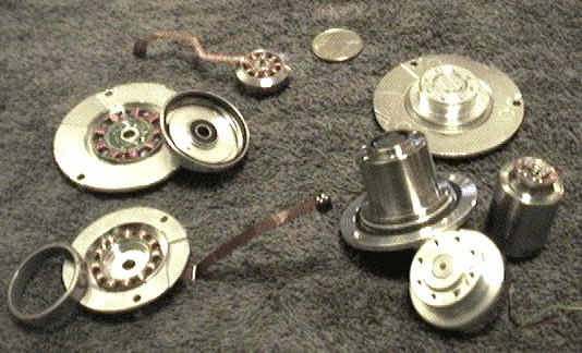
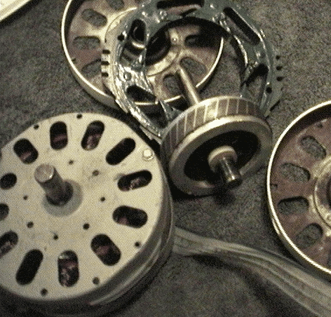
Finally we see some floppy drive motors -- the first one is from one of those old 5.25" drives. They have a lot more coils, and a flywheel is needed to help keep the speed regulated, since floppy disks turn rather slowly and themselves have almost no weight. Most often the flywheel is combined with the rotor by making the rotor a large diameter, and using a heavy metal sheild. Often, as we see in the second motor, some of the coils are missing from the stator to make room for sensors. The controller is usually on the circuit board attached to the motor.
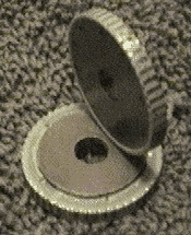
The third floppy motor shows us a more rare configuration: an "axially polar" motor, where the stator is simply coils glued onto the circuit board and the rotor is a flat disk. They work the same -- the only difference is the direction that the magnets/coil pairs are pointed. Though these motors tend to have bearings, they do not deal well when the axle is pulled at an angle -- there is enough bend in the metal frame for the flywheel/rotor to scrape. This motor also shows us another occasionally encountered trait of PM motors -- sometimes you find them where there is no core inside the coils. A steel core is usually used to enhance the effect of the coils, but it doesn't have to be there. (This would be called an "air core.")
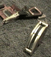
Transverse flux (sortof)
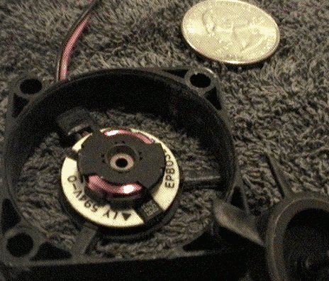
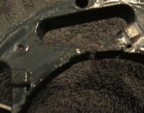
A new type of motor started to appear in newer CPU fans a while ago. These are strange animals. They are neither "axially polar" nor "radially polar" like the motors above. Looking at it it might boggle your mind at first. This is (almost) a "transverse flux" motor. Note how the coils simply circle around the stator rather than pointing towards the rotor. One would think this motor could not work at all, because in order to attract the poles in the rotor (which is the same as any other rotor) the coils need to make magnetic poles near the rotor.
The secret is those metal clips on the coil. They are made from steel and they guide the magnetic field from the middle of the coil out to the edges near the rotors. So the effect is essentially the same as a traditional PM.
Steppers
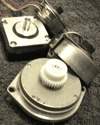
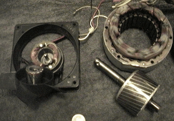
Stepper motors are (usually PM) motors that are used when precise positioning is needed. Here's a nice page on them. There are two major types in everyday use. The first shown is a more classic stepper design, and can still be found driving the heads of floppy drives. It has a central rotor with coils around the outside, except unlike the PM motors above there are more poles on the rotor, and there are two sets of overlapping coils -- in this case, one towards the front of the stator and one down in there where you can't see too well. The second set is twisted 1/2 of the way so that the coils on it cover the spaces between coils on the first.
Stepper motors are good at holding stuff in place without using any power to do so -- the steel in the stator around which the coils are wrapped is attracted to the magnets so the motor will not spin without force. Stepper motors are almost never found without a steel core inside the cables because this ability to hold their place is important -- in fact it is where they get their namesake. (In other words, they use stator "grab" as described below in the generator section.)
If something needs to be held in place really firmly, you can turn on the power to the coils to get more holding power. If you want to move clockwise, you can power up the coils in that direction on the second overlapping set. If you want to move counterclockwise, you power the other set of coils on the second set. Then after the motor moves halfway between the coils on the first and second set (and you can hold the motor in this position, too, though it costs power to do so) you simply turn off the coils in the first set. When it gets to the point of locking on the second set of coils, you can turn all the magnets off and the motor stays there.
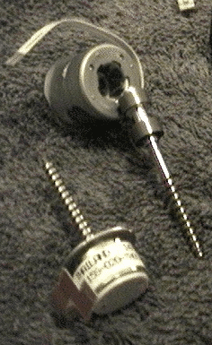
I hope you got all that, because most steppers are even more complicated. The next few shown come from very old hard drives and from bubblejet printers and fax machines. If you open them up, you get a surprise -- they have teeth!
These motors are called "hybrid steppers" and boy are they hybrids. They use ideas from the "transverse flux" motors and combine them with the traditional stepper motor (which one could argue is itself, in turn, a hybrid between traditional PMs and the reluctance motors described below.)
First let's look at a the stepper rotor. It's a donut magnet, like you might find in a speaker -- it has poles on the flat sides. On each side of the magnet a steel gear-like disk is placed. This guides the pole out to the teeth of the gear -- so we have a lot of tiny north poles on one side, and a lot of tiny south poles on the other. But there's a twist -- quite literally. The two gears are rotated so that the teeth of one gear are between the teeth of the oher gear. This is a lot like the way the metal tabs on the "transverse flux" fan motor we described above are arranged, except that it uses a permanant magnet instead of a coil.
What's been done here has been done for manufacturing purposes -- flat donut magnets are much easier to make than magnets with hundreds of radial poles. However, in this case we are more truly using "transverse flux" because the north poles and the south poles are seperated by a vertical (axial) gap.
If we tried to use this rotor the same way the floppy head stepper does, though, we would need a whole lot of really tiny coils -- one for each tooth. This is where the gap comes in handy, and to understand why we look at horseshoe magnets. Horseshoe magnets, you may recall from cartoons, are magnets that are bent like a horseshoe so that the north and south pole are beside each other. This makes them much stronger when it comes to picking up steel objects. Why? Because steel likes to do something called "completing the magnetic circuit." With a horseshoe magnet steel likes to touch both poles, bridging the gap between north and south poles. If there was no empty gap between the north and south pole, and you dropped a bolt on it, the bolt would end up in the middle, between the poles. This is shown happenning here with a magnet that has a north and south pole on the same face:
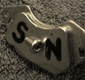
So why does a bolt stick to a normal magnet on the pole, and not on the side, between the poles? Well, that's because the magnetic field is wrapping around the whole magnet -- and as it goes around the magnet it covers a larger area of space, so the magnetic field is more dispersed, and much weaker for it. The bolt prefers to be in a place where it can touch more of the field -- where it is stronger and more concentrated -- which is at the pole where it comes back together in a small area of space. In horseshoe magnets the field jumps more or less straight from one pole to the other, and is as strong between the poles as it is at the pole.
So now let's look at the stator. The stator is like a normal motor stator, except the cores sticking out from the coils also have teeth. These teeth are in special places if you look at how they mesh with the teeth on the rotor. If the teeth of one stator core are "touching" the teeth of one of the rotor's "gears", then the teeth of the cores beside it are not. Since the rotor is twisted, that means that when one core is "touching" the rotor's north pole teeth, the ones beside it are "touching" the rotor's south pole teeth.
So think about the horseshoe magnet we just discussed. The stator core is acting like the bolt. It is completing the magnetic circuit between the rotor's north and south gears. However, that means that the magnetic circuit has to go through the core (and through the middle of one coil,) around the outside of the stator, and back through another core (and through the middle of another coil, backwards to the first) in order to get from north pole to south pole. By putting electricity into one or the other sets of coils, we can override the horshoe magnet and choose which pole, north or south, is more attracted to it, and that causes the rotor to move and bring the opposite pole close to the stator teeth.
OK maybe I lied/simplified a little, but it was for your own good. In actuality the teeth on the stator are positioned so that not only are the teeth in the next core not touching the same gear teeth, usually the ones on the next one over from that are not either -- only one pair of stator cores is touching the north poles, and only one pair is touching the south poles at any given time (these motors will have 6 or more cores, more often 8, so the other cores are stuck somewhere between.) That allows us to decide which direction the motor will spin.
What's important to note here is that the rotor does not have to turn much in order to "reverse the flux." All it has to do is turn one-half rotor tooth. Since we can build these teeth as precisely as we can cut simple steel, we have a very precise stepper motor that has served as the base of precision computing equipment -- positioning dots of ink on paper to withing 600 dots per inch, for example.
There are numerous other advantages to this ingenious motor design, but I'll hold those off until we talk about generators below. I would highly recommend these motors as geek toys/curiousities, by the way -- you can light a LED with a twist of the fingers just by plugging it into the coils, and if you short the coils they get much harder to turn. It's great fun to impress your scientifically illiterate friends.
One final thing to note about stepper motors is that they are known for containing simplifying or performance enhancing winding tricks. Very often a stepper motor coil is "bifilar" meaning it is two coils wrapped together. That is why they have so many extra wires -- extra wires on normal motors are usually to bring sensor data back to the controller. Steppers don't need sensors -- they are trusted to hold their positions precisely. It is very rare to find a wire into a stepper motor that is not directly attached to a coil.
Squirrel Cages
Most of the motors that run directly off a household AC outlet are squirrel cage motors. You can find these in fans, vacuum cleaners, power drills, and other high-power appliances. Shown are motors from some fans. These have a stator around the outside, and inside have a weird looking cylinder made of two kinds of metal, usually melted together. If you get a really old one, like the first one shown, you may find that instead of melted-together metal there is copper wire wound between gaps in the stack of steel plates. But these wires don't actually go anywhere, so how does this thing work? Pure evil, is how.
Seriously though, the stack of steel plates is made to have a higher resistance to electrical current than the wire (or melted metal) inside the gaps. That means that in the presence of a moving/changing magnetic field, electricity likes to run around in circles inside that wire. Those wires have very low resistance, and once that electricity starts going around inside it will continue to run around in circles for a while. Since it is going in circles, it generates it's own magnetic field (opposing the changing of the field that created the electrical current in the first place.) So suddenly this inert mass of metal is pushing against changes in the magnetic field created by the stator. We've created a second set of electromagnetic "coils" in the rotor, without applying electricity directly to the rotor.
When the metals in the rotor are melted together usually the other metal is silver colored, I'm guessing aluminum. It's basically the same thing as the copper wire one.
So this rotor doesn't like to have it's magnetic field change -- and since the stator has a changing magnetic field, it will prefer to turn and "chase" the stator's field rather than change it's own magnetic field to match. However, because the rotor has various paths for these circles to form in, it can and does (one could almost say "cooincidentally" if it wasn't engineered this way) reconfigure itself. So if the rotor cannot move fast enough to catch up with the field that the coils are making, the electricity flow will change instead. It's all pretty confusing, but the end result is that the rotor can turn more slowly than the AC current in the stator says it should. That means no sensors or fancy controller is needed to help this motor start up from a standstill, and you can change the speed of the motor just by weakening or strengthening the amount of AC power that gets put into the stator. In a house fan, with a three way speed switch, this is done with the "bifilar coil" trick. Extra co-wound coils are switched into the circuit to increase the amount of power, or taken away to reduce it.
Just because this motor can speed up on it's own without a controller, though, does not mean that it knows how to pick a direction. The second motor shown comes from a reversible house fan -- it had a button where you could choose to blow air in or out of the window. Notice the way the coils are wrapped -- a lot like the steppers we talked about above. Each coil circles more than one core. In this motor, the direction is controlled by "phase delay." One half of the AC power from the wall plug goes directly into one set of the coils -- let's say the ones on the outside. Another half goes into a simple capacitor. This causes a short delay in the AC wave, and the delayed wave is fed into the other set of coils. If one set of coils leads the other, the rotor will go in one direction. If you switch and put the capacitor on the other set of coils, it goes the opposite way.
All that's well and good -- but manfacturers are always looking to pinch pennies, and that's why they invented the third variety of squirrel cage motor shown, very common today in house fans. The use of this motor is the reason why most house fans do not have a reverse switch anymore, and for other reasons we get into below, it's even more evil than the rest of the squirrel cages.
This is called a "shaded poll" motor. First note the shape of the stator core -- part of it is cut away, moving the magnetic field to one side of the core. The second part is harder to see unless you take the stator apart.
In each core, off to one side is a notch, and a ring of copper goes through this notch and around the near side of the core. This works in much the same way as the rotor -- when the core has a magnetic field change, electricity starts to flow around this copper ring. When the core changes it's magnetic field, say from north to south, this ring of copper wants to stay the same way for a little while, and will do so until it cannot resist the field in the rest of the core. That means the core has a spot in its field on one side of the core that lags behind. So the rotor is pulled in one particular direction, much like the double set of coils do in the reversible fan, except that it can be manufactured more cheaply without that extra set of coils.
DC brush
Next to the squirrel cage, these motors are probably the most common ones in your house. They are used in CD drives, in cordless power tools, and in battery-powered toys. A good diagram is here.
They look a lot like a traditional PM motor inside, except the position of the magnets and the coils are reversed -- the coils are usually on the rotor and the magnets are on the stator. Because the coils are on the rotor, we can't just attach to the ends of the wire -- they are spinning. So electricity is sent to a pair of brushes that scrape up against contacts on the base of the rotor.
There are usually three coils on the rotor, and the way the contacts are arranged, the coils are connected, disconnected, and then connected backwards as the rotor turns. It's like clockwork, with one critical difference: it works at any speed. You can increase the speed or power of the motor by feeding it more DC power. You can make the motor turn backwards by swapping DC plus with DC minus. The one thing you can't do very well, though, is control the speed precisely. Since there are no sensors, the load on the motor can slow it down and you have no controller standing there to react fast and send in more power.
These motors usually have no bearings at all -- in the way they are used, they are protected by the gears used to transmit their power. The brushes, and the axles, can wear out over time, and if used at too high a speed friction will heat up the axles and start a fire.
Linear
No tour of motors would be complete without a visit to the liliputian island of linear motors, where round and round is in and out, and what goes up, must come down. These motors don't go around in circles, they go back and forth. Usually these are used when you need to position things, like you do with a stepper, except really, really fast and without worrying too much about how much power you are using to do it.
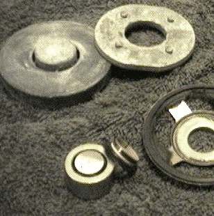
The one you are probably most familiar with is the audio speaker, shown first. Inside the donut magnet is a coil that can move back and forth -- towards the north or south pole of the donut, based on which way electricity is flowing in the coil (and how much electricity is flowing.) Well, maybe it isn't that simple -- if you look close you can see that the magnetic field is actually being guided around by steel. Remember the whole horseshoe magnet discussion? Well stuff like that goes on in speakers too. But other than that they are very simple devices.
This one is a "voice coil." It gets it's name from an old device that was used in telephone systems. You may have more of these in your home than you realize -- it's what moves your computer's hard drive head around and makes that clicking noise when you boot your computer. It works basically the same way as the speaker, except that there is usually a detector built onto the arm it turns that helps the hard drive position the head very accurately.
The first one shown in this photo is what aims the laser in your CD drive. If it were not for these, then CD drives would have to use a super-precise stepper motor instead of a DC brush motor to position the head. Instead, they let a DC brush motor, along with a sensor, do the grunt work and this linear motor does the detail work. The second one here is an old-style relay -- just a big electromagnet that throws a mechanical switch. How primitive!
Alternators
A car alternator is also a motor -- ok, well, a generator -- but they are mostly the same animal. I don't have one open to show you but there are plenty of photos on the web. It is sort of a combination between a DC brush motor and a squirrel cage motor. In place of the squirrel case rotor, there is a rotor with a second set of coils like the one in a DC brush motor. This is essentially a squirrel cage where we don't want to let things run automatically. Instead we control the magnetic field in the rotor by feeding some of the power from the stator back in there. This makes the device very adjustible, and allows us to stabilize the voltage of the power we get from the alternator, regardless of how much it is loaded.So no, your car alternator doesn't generate any "extra" power when you turn off your headlights and radio -- nothing is thrown away. The magnetic field in the rotor is simply reduced, making the alternator much easier for the engine to turn.
The race to the bottom
I mentioned above that the shaded pole squirrel cage motor used even to this day in everyday house fans wastes power. Actually that's true of squirrel cage motors in general. How much power is wasted? Well, by some estimates, the older capacitor-based types throw away 35% of the power that comes out of your wall socket, while the shaded pole variety wastes more power than it uses -- 65% of the power it inhales is just turned to heat and digits on your electricity bill.It seems as though the bargain-hunting public managed to hunt themselves up a raw deal on that one. There are stories like that in every industry, by the way -- where penny pinching engineers fooled "savvy shoppers" into taking an inferior but cheap product -- but that's beside the point of this here tour, and I have to get you back to the gazeebo and pick up another tour group. But before you go...
Have you seen this motor?
This next motor design deserves to be on a milk carton, because it's a modern-day mystery as to why you don't have tens of them in your house, taking the place of squirrel cage motors and PM motors. It's name is the "switched reluctance" (or "variable reluctance") motor, and it was last seen in the 90s wearing an off-white Emerson washing machine.I won't go into too much detail on these motors because there is an excellent writeup on them here and some history in this old article here. They basically work using the horseshoe-magnet effect talked about above -- a toothed metal rotor moves to complete the magnetic circuit between coils in the stator when they are turned on.
What's interesting about them is that they are very simple to manufacture, do not require magnets, and can be very efficient and versatile with some stepper-motor-like properties alongside high-speed operation. I suspect that they are what Raser Technologies is marketing, though that's just a guess.
The only major drawback -- and it's a benefit as much as a drawback if you consider versatility -- is that they need a fairly complex controller system to make them run smoothly and efficiently. However with modern electronics so cheap these days, it is hard to see why this would be a deal-killer for the technology considering all their other advantages.
Back to trash hacking main index
Converting to generators
So say you wanted to convert some of these motors to a generator. What makes a good generator? Actually let's flip that question -- what makes a poor generator?- High winding resistance
- Motors with a high resistance in the coils will not be able to provide a lot of current. A motor will put it's maximum power to a load that has the same resistance as the windings -- and in doing so will waste 50% of the generated power. So you want a coil resistance rather lower than your expected load resistance.
- Low winding count or weak magnets
- A low number of winds in the coils or weak magnets will result in low voltages. Voltage has to be high enough to get through two diodes without losing too much power, or your efficiency will be low. Unfortunatley a high winding count will bring up resistance -- see above -- so it's a trade-off.
- Low number of "flux transitions."
- Motors that only change the magnetic field across the coils a few times per rotation may require a high RPM to generate decent voltage. Even if a good voltage appears at low RPM, a low frequency AC power source will not be as efficient to feed through a transformer, and will require more capacitance in the rectifier to smooth out for use as a DC supply.
- High stator grab/lock
- For applications like wind where power may come in bursts, motors that "grab" onto the magnets too hard will prevent the apparatus from spinning up until the wind overpowers the grab. By the time the device "spins up" the burst of power may be almost over. This affects low-resolution steppers most, and some AC motors. With a proper configuration of poles and stators (a ratio that doesn't match up, like say 3 coils to 8 PM poles) stator grab is reduced. Most newer PM 3-phase motors are like this, and many DC brush motors are as well because of their design, but older AC motors where coils and poles all line up can have very bad grab.
- Poor bearings
- Many motors have a lot of friction in the bearings, because they are not designed for continuous use. Many bearings are wimpy and would have to be isolated from stress mechanically. Some motors have bearings that require axial pressure to be applied during use, and others react bad to axial pressure.
- Difficult mounting
- Don't discount the challenge of mounting a motor. A lot of motors have a middle axle that is tied to the stator, others have a section tied to the rotor. The most versatile motors have a rotor-tied object on both sides and can thus be "ganged" in groups by running a common axle through the middle of many motors (or bolting flywheels to flanges.) I'll be working in the near future on building a neat annotated table showing the comparitive advantages and disadvantages of motors salvaged from various sources, including those above, when it comes to using them as generators.