Sometimes this site gets linked from popular hacking blogs.
It's served off a cable modem. If I notice a traffic spike, I'll
either offload the images to imageshack temporarily or in the meantime
if you have trouble loading, go to a wayback machine archive.
The dirt-cheap floppy-drive active solar tracking unit
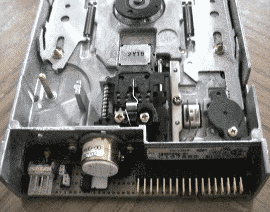 This is still pretty much a work-in-progress, but I did manage to create
a successful heliostat (sun tracker) from the above TEAC model FD-235HF
3.5" floppy drive. This procedure will likely work just fine, with a bit
of adaptation, on any drive new enough to have CMOS logic on its chipset.
This particular drive (probably a lot of others) only needs a single 5V DC
supply. It has two boards, one with the stepper and main logic, and one
with the spindle. The first is the only one needed, and it draws 0.1 Watt
with the motor off, and 1 Watt with the motor running, so it should be
easy enough to power with a cheapo hobbyist 5V solar cell if stand-alone
operation is needed, perhaps a sub-watt one if a large capacitor is supplied
to build up enough juice for a motor step over time.
This is still pretty much a work-in-progress, but I did manage to create
a successful heliostat (sun tracker) from the above TEAC model FD-235HF
3.5" floppy drive. This procedure will likely work just fine, with a bit
of adaptation, on any drive new enough to have CMOS logic on its chipset.
This particular drive (probably a lot of others) only needs a single 5V DC
supply. It has two boards, one with the stepper and main logic, and one
with the spindle. The first is the only one needed, and it draws 0.1 Watt
with the motor off, and 1 Watt with the motor running, so it should be
easy enough to power with a cheapo hobbyist 5V solar cell if stand-alone
operation is needed, perhaps a sub-watt one if a large capacitor is supplied
to build up enough juice for a motor step over time.
A few nuances about this drive. The first is that when power is applied,
the head auto-advances to one side. If the head assembly is removed, the
motor will just keep spinning -- it is neccessary to interrupt a photoswitch
under the head to get it to stop. The second is that if for some reason the
spindle board is attached, the stepper will not run unless the button that
runs the spindle motor is depressed. The third is that there is a software
lock on movement in one direction -- the stepper will stop after a certain
number of steps, and if one wanted to get it to step further in that direction,
one would have to step in the opposite direction once, and interrupt the
photoswitch to reset the counter. I decided to leave the motor and head
assembly intact and just work with the limited number of steps available
so that I wouldn't have to mess with all that.
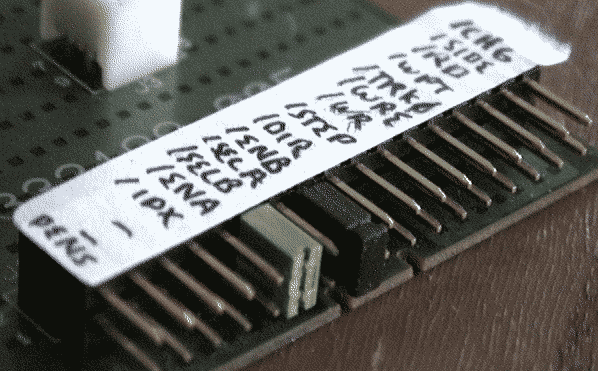
First I jumpered a couple pins permanantly -- /SELB and /ENB. This model
seems to require both to be pulled low before it will run the stepper.
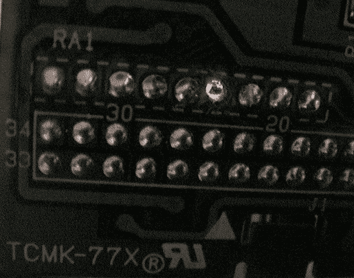
Next, being careful not to cut the trace, I cut the pin on the pull-up resistor
package for the /DIR input. This input leads into the ASIC, and this puts
the gate into a floating state. I needed to do this because I needed a very
sensitive input here to drive off of photodetectors. I bored through the
solder as shown above (where the daylight is showing through) and then
checked that there was now no connection to Vcc. A bit of glue might be wise
here to insulate things.
 Next I needed some photodetectors, so I decided to abuse some yellow LEDs.
Green may work but red is too low power. I decided to use the variety with the
tight light cone, since I'm not really worried about having to recover lock
on the sun from a large error angle, -- the system will auto-track to
the sunrise when it is first powered on and should stay locked, though I'll
have to see if it can ride through heavy cloud cover.
Next I needed some photodetectors, so I decided to abuse some yellow LEDs.
Green may work but red is too low power. I decided to use the variety with the
tight light cone, since I'm not really worried about having to recover lock
on the sun from a large error angle, -- the system will auto-track to
the sunrise when it is first powered on and should stay locked, though I'll
have to see if it can ride through heavy cloud cover.
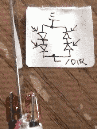
Two pairs of two LEDS are in series, and oppose each other, so that if the
system overtracks it will start stepping backwards. There is a bias here,
since the gate on the ASIC turns on at a certain positive voltage, so the
assembly will have an offset from pointing directly at the sun, but that
can be compensated for mechanically.
The LEDs are inserted into some jumpers to connect them, and these assemblies
are tie-wrapped to opposite sides of a shiny PC slot cover which will provide
shade and reflection as appropriate. An old case front-panel wire is used as
a plug to insert the signal into the /DIR input. A few fragments of plastic
from the floppy drive door are used as spacers, and once the whole thing is
together, a liberal dose of glue provides waterproofing and firms up the
structure.
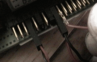
For quick testing an easy way to provide an occasional pulse to the /STEP
input was to connect the spindle motor and then wire the /IDX output to the
/STEP input. But using a spinning motor for nothing more than an electrical
clock signal is kinda silly and defeats the purpose (to reduce power
consumption.) I needed a clock somewhere in the 1HZ to 0.01 HZ range.
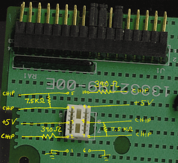
The clock didn't need to be particularly accurate. I decided to use the
connector from the read/write heads to build this nice a-stable multivibrator
circuit. It's a cool circuit because, being symmetrical, it's pretty
easy for even the casual electronics hacker to understand and it fit well with my other reason for using the read/write head connector: to utilize some of
the onboard components, in this case resistors. The diagram shows you where
the pins on the connector go. As you can see we have two pairs of resistors,
one 7.5KOhm and one 390 Ohm -- within a reasonable range for the circuit, if
we upsize the capacitors a bit.
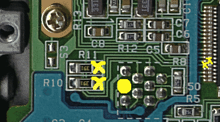
We'll be removing the LEDs from the circuit. Most of the circuit can be built
on the connector, but one part needs a bit of work on the back of the board.
The chip-side ends of those 390 Ohm resistors need to be connected to +5V. I
soldered, but for those that don't have the ability to do that, a little wire-wrapping around the microchip pins might do the trick. I have not found it
to be necessary to cut the traces to the microchip -- it's all CMOS so there's
negligible bias current in the read/write circuit differential comparitors
and output drivers. The diagram shows with X's the points at which +5 volts
needs to be connected -- either at the resistors (the big X's) or at the
chip (the tiny X's) you don't have to do both. The big dot shows you
one place to pick up a +5V power supply -- in this case it's the backside
of one of the pins on the connector we will be building the circuit on.
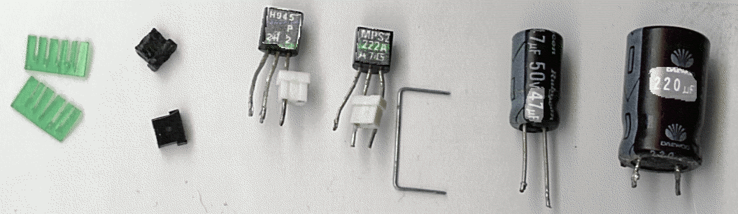
These are the additional materials needed to build the clock: The first
bits are some soda-bottle plastic cut in a comb to fill in the spaces
between pins in the connector, which is meant for a ribbon. Those
don't have to be perfect as long as the teeth are about the size of the
space between the pins, and some material has been removed. I made both the
teeth and back a bit longer than needed and then trimmed to size. Next
are four small jumpers, an NPN BJT with the base pin on the side (ECB),
and an NPN BJT with the base in the middle (EBC). If two different pinouts
can't be found some extra finagling is required to get it all together. The
transistors need at least as much connector remaining on them as shown.
(The white jumpers are on the bases.) Next is a staple, with the glue
scraped off, to be used jumping pins. Finally two capacitors. Because
I don't care if the thing steps in even intervals I used two different
sized capacitors here -- they physically fit better. The
ratings/markings are highlighted for anyone anal retentive enough to want
to follow this design exactly.
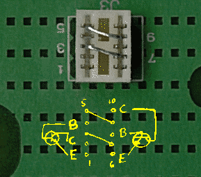
Next I cut the staples in half and used it to jump one side of each
7.5KOhm resistor to the +5V power leads, as shown. Also shown is a diagram
of the pins into which the collector, base, and emitter of each transistor
will be placed. On the collector and base of each transistor, I put
one of the little jumpers halfway up the wire to act as a socket for the
capacitors. Then the capacitors are attached (by pluggingthem into the
second socket in the jumper) between the base of one transistor and
collector of the other, and visa versa. The negative side of each
capacitor should attach to it's respective base.
I'll be adding more photos and instructions on building the clock circuit as I build a second one.
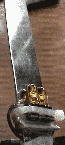
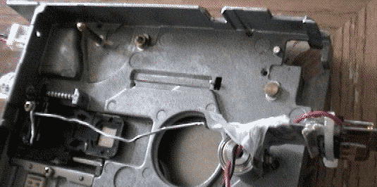 I haven't yet found the easiest way to mechanically link the head assembly
to provide 180ish degrees of rotation for the photodetector, and a second
linkage to provide 90ish degrees of rotation for a reflector. Though it
is tempting to ditch the head assembly in favor of a gear, it does do
a good job of isolating the stepper from torque induced by wind. Keep in
mind that this is a pretty small steppor, so without a lot more gearing,
it won't be able to directly drive anything that is too heavy. The above shows
a simple test setup using some picture hanging wire and a hard drive
head bearing (a bearing here is a bit of overkill.) Right now I'm
leaning towards the prospect of an opposing-tension drive using some anchored
winding wire on a spool of the appropriate diameter.
I haven't yet found the easiest way to mechanically link the head assembly
to provide 180ish degrees of rotation for the photodetector, and a second
linkage to provide 90ish degrees of rotation for a reflector. Though it
is tempting to ditch the head assembly in favor of a gear, it does do
a good job of isolating the stepper from torque induced by wind. Keep in
mind that this is a pretty small steppor, so without a lot more gearing,
it won't be able to directly drive anything that is too heavy. The above shows
a simple test setup using some picture hanging wire and a hard drive
head bearing (a bearing here is a bit of overkill.) Right now I'm
leaning towards the prospect of an opposing-tension drive using some anchored
winding wire on a spool of the appropriate diameter.
Coming soon (OK, well, someday)
I'll let you know what I come up with to tuck the corners of this design.
By the way, this brings up a point. Even new, though why anyone would
buy one new is a mystery, a floppy drive costs like $6. The other compenents
used here are pennies. That's what economy of scale can do.
A full drive system for a heliostat with accuracy
sufficient to reflect sunlight onto, for example, a solar hot water
collector to double or triple its output, should be manufacturable for
well under $10, minus the gearing and structure, were heliostat producers
to target a market that doesn't need insane climate tolerances. That is,
people who can afford a bit of time to fix stuff once every five years or so
because they only have 20 of them.
This
guy gets it.
Back to trash hacking main index
Docs needed
If anyone can come up with the docs for the controller chip on the pictured
floppy, that would help me a lot. Even just a pinout with functional
description. The chipset is TAEC 3975-00 a.k.a. tb6005F a.k.a. T4A34F.
Other chipsets I'd also be interesting (from other floppies) are:
5529-10 a.k.a. BH9506bks2, 5529-60 a.k.a. bh9503bks2, ncl022, cxa1500Q,
and the ba6600k/ba6485p/tc8617BF combo set.